

Importance of Adhesion
Poor coating adhesion can easily result in cracking or peeling, which not only affects the product's appearance but also undermines its protective function. Therefore, it is essential to use suitable and scientifically proven testing methods to assess the coating’s adhesion strength. Adhesion testing is one of the most widely used methods for evaluating coating strength and is a key technical indicator in assessing the performance of coatings or coating systems.

Adhesion Testing Methods
Common methods for testing coating adhesion include the cross-cut method, x-cut method, and pull-off method. In the automotive industry, the cross-hatch and scratch methods are the most commonly used.
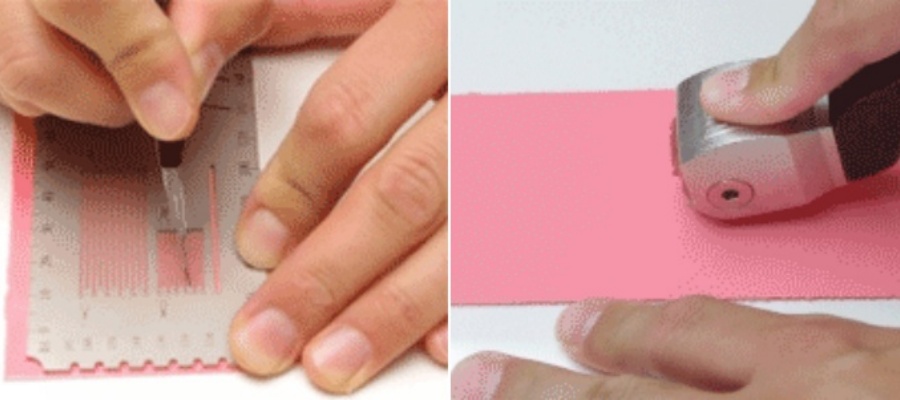
The cross-cut method for determining coating adhesion originated from ISO 2409. ISO 2409 recommends the cross-cut method (Fig. 1) for evaluating coating adhesion, which is commonly used by automotive manufacturers. In addition to the cross-cut method, ASTM D 3359-2009, Standard Test Methods for Rating Adhesion by Tape Test, also recommends the x-cut method (Fig. 2) for coatings thicker than 125 μm.
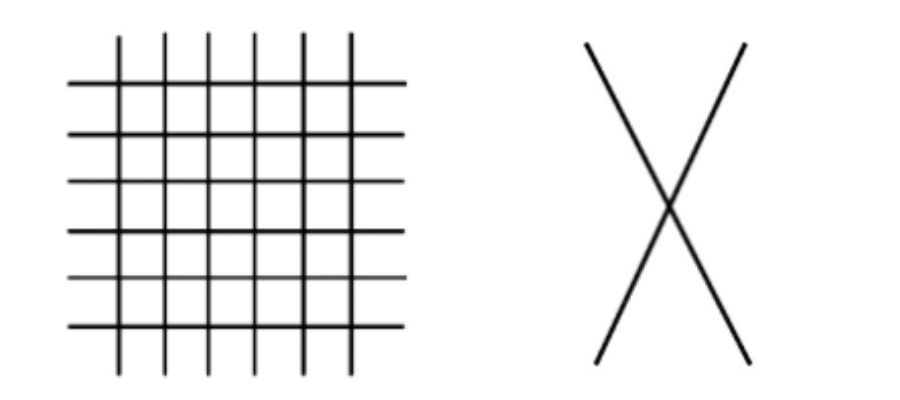
Figure 1. Cross-cut diagram Figure 2. X-cut diagram
The cross-cut method
ISO 2409, as a widely recognized method for adhesion testing, is referenced by many equivalent or related standards, including GB/T 9286-1998 Paints and Varnishes-Cross cut test for films, AA-0180-2010 Cross Test, and D 25 1075-1997 Adhesion Test for Paint Coatings—Cross-Cut Method, among others.
ISO 2409-2013 involves the cross-cut test, which uses either a single-blade or multi-blade cutter. The spacing of the cuts is determined based on the actual thickness of the coating. Six equidistant parallel lines are then made in two perpendicular directions to form a grid. For metal/plastic substrates and wood/plaster substrates, the cut spacing ranges from 0 to 60 μm. The cuts should penetrate the coating down to the substrate, but the penetration into the substrate should be as shallow as possible.
ISO 2409-2013, ASTM D 3359-2009, GMW 14829-2012, and other standards specify different cut spacing requirements based on the coating thickness. In addition, ASTM D 3359-2009 requires 11 cuts in each direction for coatings ranging from 0 to 50 μm. After performing the cross-cuts, any loose coating should be brushed off with a soft brush, then a specified adhesive tape is applied over the cuts, pressed down, and left for a certain period before removing the tape and the detached coating. Although the definitions for cut spacing may differ slightly between standards, the grading criteria for the test results are generally the same, as shown in Table 1.
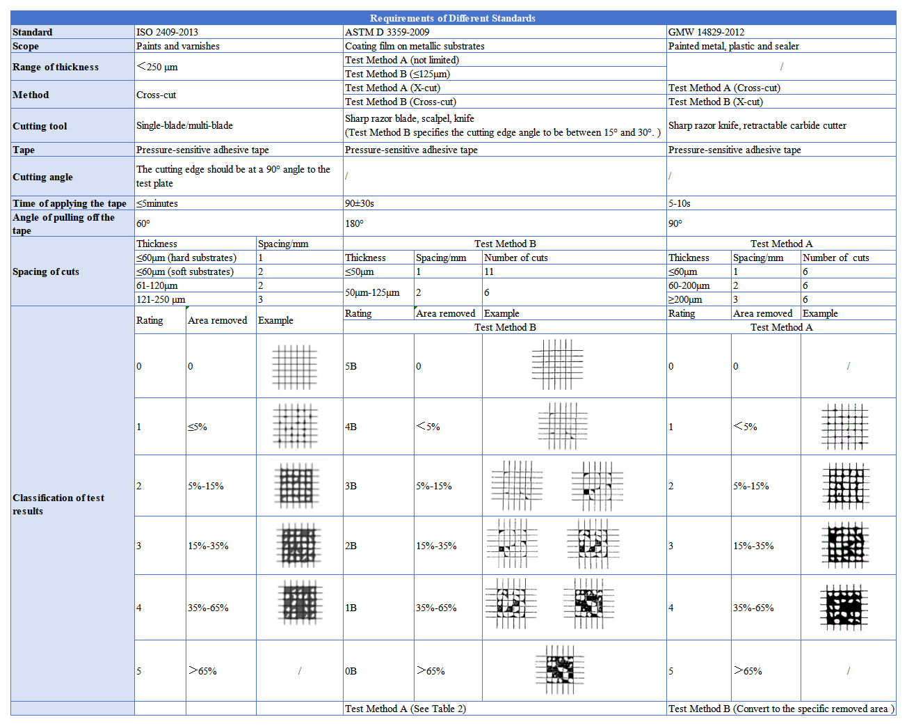
Table 1
The X-cut method
ASTM D 3359-2009 introduces the cross-cut method, where two 40 mm straight lines are drawn on the sample at an angle of 30° to 45°. The integrity of the coating is checked by observing whether the metal substrate is visible through the cuts. Then, Permacel tape is applied over the cross-cut area, pressed for (90 ± 30) seconds, and quickly pulled off in a 180° direction. The coating retention in the cross-cut area is then evaluated. In contrast, GMW 14829-2012 (General) Method B (cross-cut method) requires 75 mm long cuts. The evaluation methods are also notably different: the former relies on visual assessment, with the rating method shown in Table 2, while the latter calculates the retained coating area within a 1,500 mm² (20 mm × 75 mm) cross-cut region to determine the rating.
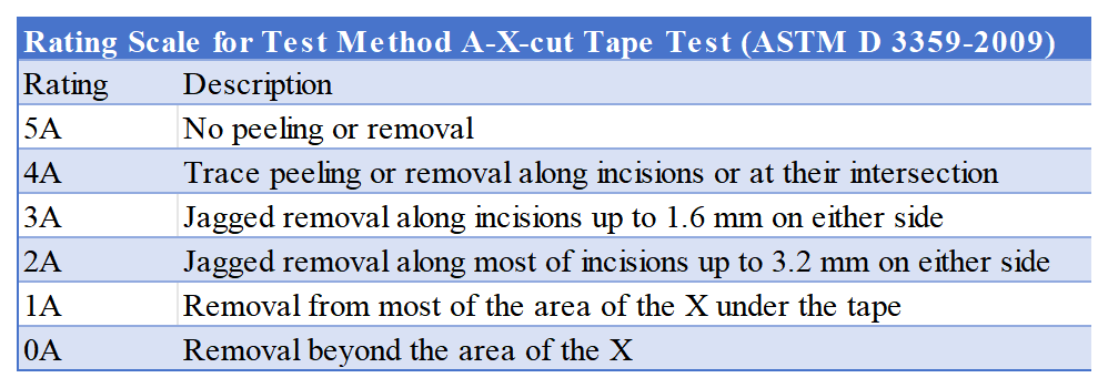
Table 2
Figure 3 shows different types of paint peeling at the cut areas: A indicates uniform paint removal along the cuts; B indicates paint peeling at the intersections of the cuts; C shows small paint chips peeling off that are not in contact with the cuts; and D shows small paint chips peeling off that are in contact with the cuts.

Figure 3
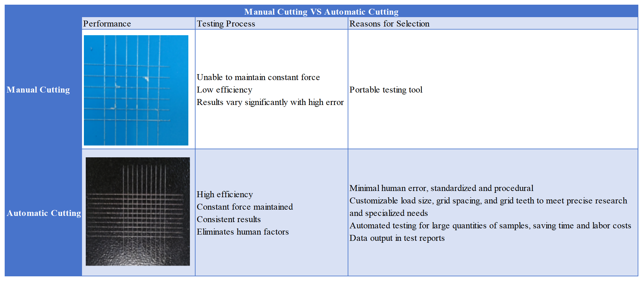
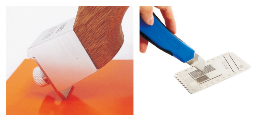
Manual Cutting VS Automatic Cutting
Manual cross-cut involves manually scoring the coating surface with a blade or cutter to create a grid pattern. The operator controls the pressure and angle during the process, which can vary slightly with each test. This method is commonly used for smaller-scale or less complex testing.
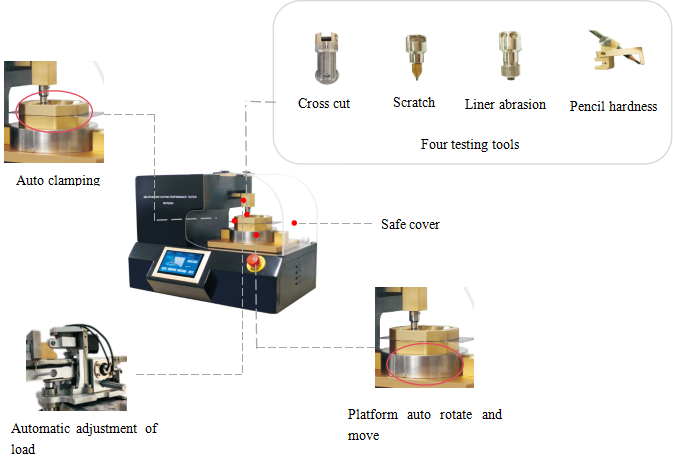
On the other hand, automatic cross-cut uses a machine to apply consistent pressure and speed, ensuring higher precision and repeatability. The automatic system creates uniform grid patterns with minimal human error, making it ideal for more consistent and accurate results.
Comparison Table of Manual Cross-cutting and Automatic Cross-cutting